
Lighting Angles That Expose Bad Fixture Junctions
Position lights by the joint, not the fixture. A grazing angle flattering enough to make polished chrome or nickel read as a solid, continuous surface will also throw a hard shadow across every grout line, caulk bead, and escutcheon gap within about 150mm of the fixture. If the trim and tile aren’t coordinated to a tolerance the light can’t exaggerate, no beam angle fixes it after the fact.
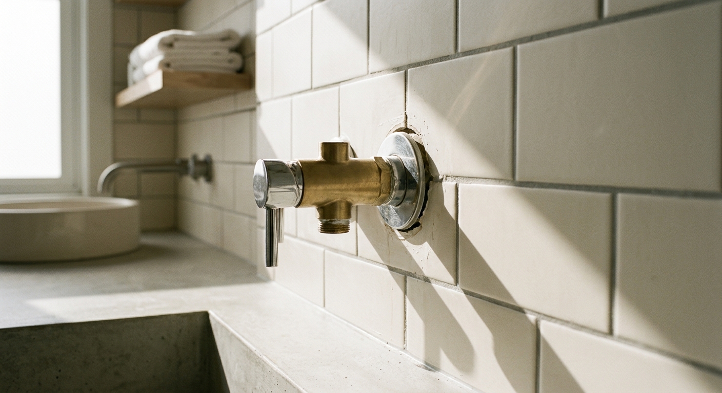
Why Polished Metal Reveals Every Surface Flaw
Polished nickel and chrome are specular finishes. They don’t scatter light the way a brushed or matte finish does, so they return a near-mirror image of whatever is illuminating them, including the light source itself, the ceiling, and anything reflective nearby. This is why CRI 90+ sources matter here in a way they don’t for a painted wall: a low-CRI source will render the reflection off polished metal with color shifts that make the finish look cheap or slightly green, even though the metal itself is fine. But high CRI only solves the color problem. It does nothing about the geometry problem, which is that specular surfaces also reflect shadow edges with the same crispness they reflect highlights. A soft, diffuse light source blurs a bad caulk line. A point source sharpens it.

Grazing Angles Versus Tile and Grout Lines
Grazing light, meaning light striking a surface at a low angle relative to the plane, is standard practice for making polished metal look dimensional rather than flat. It’s also the single fastest way to expose irregular grout lines, lippage between tiles, and uneven caulk beads at a tub or shower surround. The lower the angle, the longer the shadow cast by any surface irregularity, including ones under a millimeter.
Beam angles in the 15 to 25 degree range are typical for this kind of accent or grazing application on fixtures and trim. That range is narrow enough to control spill but wide enough to wash a reasonable length of wall or fixture run. The practical issue is that this same beam angle, aimed to flatter a widespread faucet or a polished towel bar, will also graze the tile field behind it. If the installer’s grout lines aren’t consistent in width and depth, or if the setter didn’t keep the sanded caulk joint at the tile-to-fixture transition clean and uniform, that 15 to 25 degree beam will draw a shadow line directly to it.
Read More
The fix isn’t to soften the beam angle until the problem disappears, because that also kills the modeling on the metal that justified the fixture spec in the first place. The fix is to treat the tile layout and grout joint width as part of the lighting spec, not a separate trade’s problem. If a grazing fixture is going in, the grout joints in its field of effect need to be specified tighter and more consistent than the building standard, and the setter needs to know that before tile goes up.

Beam Spread and Rough-In Offset Visibility
Every wall-mounted fixture, whether it is a faucet, a shower valve trim, or a sconce, sits over a rough-in that was set before the finish material went on. The escutcheon or flange covers that rough-in, but it can only cover so much. A typical tolerance before shadowing becomes visible under grazing light is about 3mm of offset between the escutcheon’s finished position and the substrate penetration it’s covering. Below that, the escutcheon sits flush and reads as a clean disc or ring. Above it, the escutcheon either stands slightly proud of the tile or sits slightly recessed, and grazing light catches the resulting gap as a crescent of shadow.
Read More
This tolerance is tighter than most rough-in inspections check for. A plumber setting a valve body is working to code clearances and functional reach, not to a 3mm cosmetic standard, because nobody told them the lighting plan called for grazing light at a low beam angle. The coordination has to happen on paper, at rough-in, with the lighting layout in hand, not during trim-out when the tile is already set and the only options are forcing an oversized escutcheon or living with the shadow.

| Condition | Effect under grazing light (15-25°) | Where it’s caught |
|---|---|---|
| Escutcheon offset under 3mm | Reads as clean, no visible shadow line | Rough-in inspection with lighting plan on hand |
| Escutcheon offset over 3mm | Crescent shadow at flange edge | Trim-out, often too late to correct without redoing tile |
| Grout joint width inconsistent by more than 1-2mm | Visible waviness in shadow line parallel to grazing beam | Tile layout review, before setting |
| Caulk bead uneven at fixture-to-tile transition | Highlighted gloss variation and shadow banding | Final finish walkthrough, correctable with recaulking |
Sconce Height Relative to Mirror Silvering Edge
IES guidance for vanity sconces typically centers mounting height around 1.5m above finished floor, with adjustment for ceiling height and mirror size. That number is a starting point for even face illumination, not a fixed rule, but it’s worth holding to within a reasonable range because sconce height interacts directly with the mirror’s silvering edge, meaning the boundary where the reflective coating on the back of the mirror stops.
If a sconce sits too close to that edge, or if the mirror’s edge polishing and silvering coverage aren’t tight and consistent, the sconce’s own reflection in the mirror will show a visible seam or dark band right where the silvering runs out. This is a junction most lighting plans never touch because it’s assumed to be a mirror-supplier detail, not a lighting one. It isn’t. The sconce position determines whether that edge is lit directly enough to be noticed.
Read More
The same logic applies to polished faucets at the vanity. A widespread or single-hole faucet in a polished or warm metal finish sitting under a sconce at the wrong height will throw its own reflection onto the mirror face at an angle that draws attention to any gap between the deck plate and the countertop. When specifying warm finish faucets for a vanity with sconce lighting, the deck-to-counter seal and the sconce height need to be reviewed together, because a warm polished finish reflects the same way chrome does and the junction problem doesn’t change with the metal color.

Coordinating Electrical Rough-In With Tile Layout
The practical failure point is sequencing. Electrical rough-in for sconces and accent lighting typically happens before tile, and tile layout is frequently finalized or adjusted after that rough-in is already roughed in and inspected. When the tile setter shifts a layout to avoid a cut tile at a visible edge, the sconce box doesn’t move with it, and now the fixture centerline is off from the grout joint or tile module it was meant to align with.
Read More
This is solvable with a single meeting that most projects skip: the electrician, the tile setter, and whoever owns the lighting plan need to confirm final tile layout and grout joint locations before the electrical rough-in locations are locked, not after. On a project with grazing light planned near fixtures, this isn’t a nice-to-have coordination step, it’s the step that determines whether the shadow lines the lighting plan is going to create fall on intentional joints or on whatever the trades happened to land on.

Specifying Light Position in the Junction Detail
- Call out beam angle and mounting distance on the same detail sheet as the tile-to-fixture junction, not on a separate lighting plan referenced by sheet number only.
- Note the 3mm escutcheon offset tolerance directly on the rough-in detail, with a flag to the trade setting the valve or supply body.
- Specify grout joint width and tolerance explicitly for any tile field that falls inside a grazing beam’s throw, rather than relying on the building standard.
- Confirm sconce height against the specific mirror’s silvering edge and polish specification, not a generic 1.5m default, when the mirror is custom or oversized.
- Require a mockup or full-scale sample wall where grazing light and polished fixtures are combined on a project with tight tolerances, before the condition is repeated across multiple units.

Before issuing the lighting and tile package for construction, walk the rough-in locations against the finalized tile layout in plan and section, confirm escutcheon sizes cover the worst-case rough-in offset on site (not the drawing dimension), and get the grout joint width for any grazed tile field in writing in the finish schedule. If the sconce-to-mirror relationship is custom, request a shop drawing from the mirror fabricator showing silvering coverage before the electrical rough-in is locked. These are coordination items, not judgment calls, and they are cheaper to fix on paper than at trim-out.